Network Devices
In any network, multiple devices play crucial roles in transferring data from one computer to another. Let's explore some of these essential network devices.
Repeater
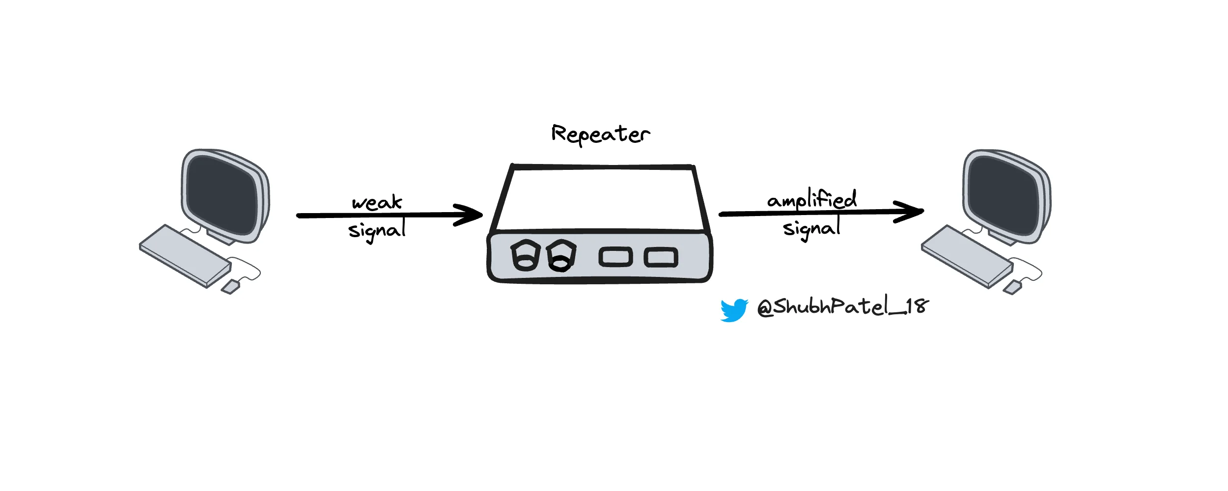
Network Repeater
A network repeater is a device that strengthens and extends the reach of a network's signal. It takes the data signal from one end, amplifies it, and sends it out again. This process increases the distance the signal can travel without losing strength. However, using too many repeaters can introduce latency and signal congestion, which might affect the overall performance of the network.
Hub
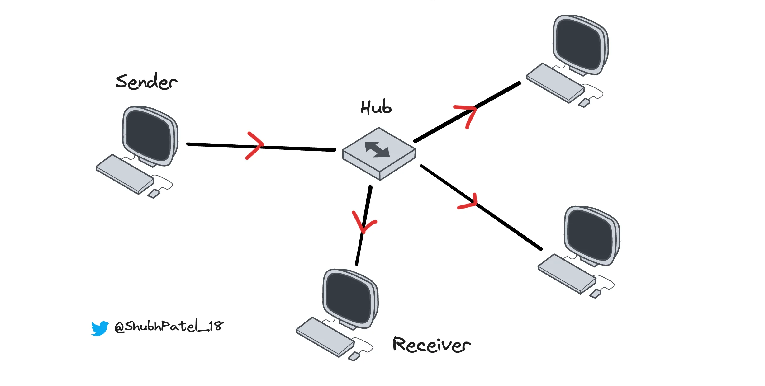
Network Hub
Hubs are often called "dumb devices," but they were a significant step forward in networking technology. A hub is a basic networking device that serves as a central connection point for multiple devices in a LAN. It receives data from one device and then broadcasts it to all other connected devices.
-
Hubs operate at the physical layer (Layer 1) of the OSI model.
-
All devices connected to a hub share the same bandwidth. If multiple devices try to transmit data simultaneously, it can lead to collisions where data packets collide and need to be retransmitted.
Devices connected to a hub share bandwidth, which can cause network performance issues if too many devices transmit data at the same time, leading to collisions and retransmissions.
Hubs are simple devices that don't analyze or filter data. They pass the data to all devices except the sender, without any form of intelligence or decision-making. This makes them inexpensive and easy to set up but less efficient compared to switches or routers.
Bridge
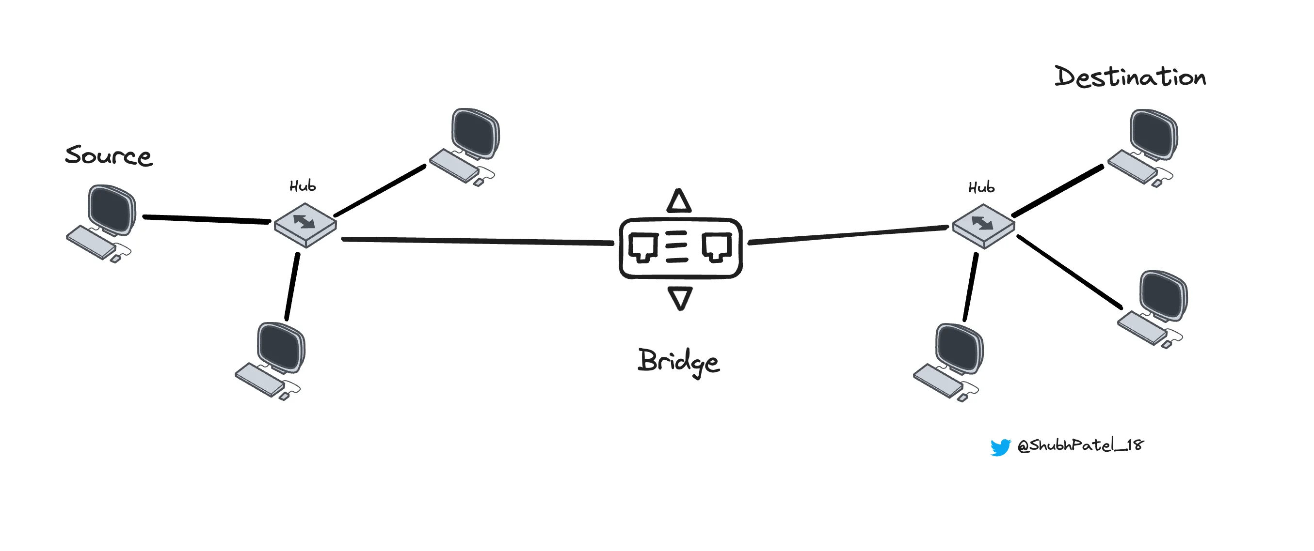
Network Bridge
A bridge is a network device that connects two or more networks. The number of networks it can connect depends on the number of ports it has, usually two or four. Bridges work at the Data Link Layer (Layer 2) of the OSI model, making them slightly more intelligent than hubs.
Bridges use a MAC Address table to keep track of devices and their respective ports.
Below is an example of what a MAC Address Table might look like. If you're not familiar with MAC addresses yet, think of them as unique identifiers for each device.
| MAC ADDRESS | PORT |
|---|---|
| 00:11:22:33:44:55 | Port 1 |
| 00:AA:BB:CC:DD:EE | Port 2 |
| 11:22:33:44:55:66 | Port 1 |
| 22:33:44:55:66:77 | Port 1 |
Here’s how a bridge works:
-
A source device sends data to its network's hub.
-
The hub broadcasts the data to all connected devices, including the bridge.
-
The bridge checks its MAC address table to see if the destination device is on another network.
-
If it is, the bridge sends the data to the hub of the destination network.
-
The hub in the destination network broadcasts the data to all its connected devices.
-
The destination device receives the data.
If the destination device is in the same network, the bridge does not forward the data to another network.
Switch
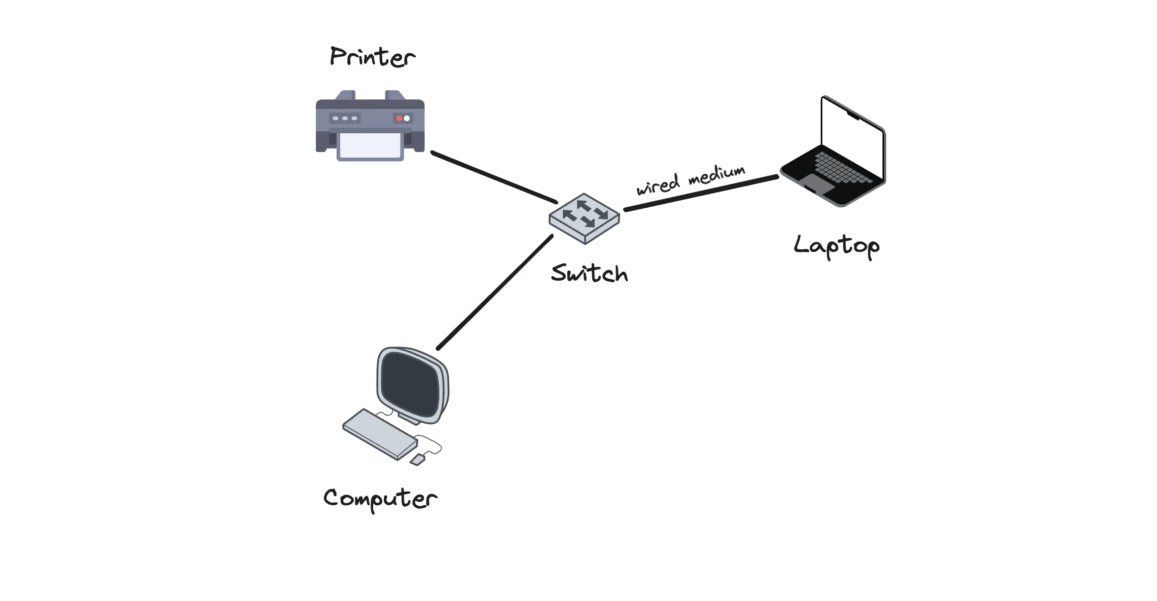
Network Switch
Unlike hubs, switches are intelligent devices. They only forward data to the specific destination device instead of broadcasting to all connected devices. This capability comes from using a MAC Address Table. Switches operate at Layer 2 of the OSI model, unlike hubs, which operate at Layer 1.
Benefits of switches include:
-
Number of Ports: Switches can accommodate many ports, connecting hundreds of devices. If one switch is not enough, you can connect another switch using one port.
-
Error Checking: Switches have mechanisms to check for errors in data to ensure it has not been corrupted.
-
Data Transmission Speed: Switches can achieve data transmission speeds up to 100 Gbps, while hubs are limited to a maximum of 100 Mbps.
Router
Network Router
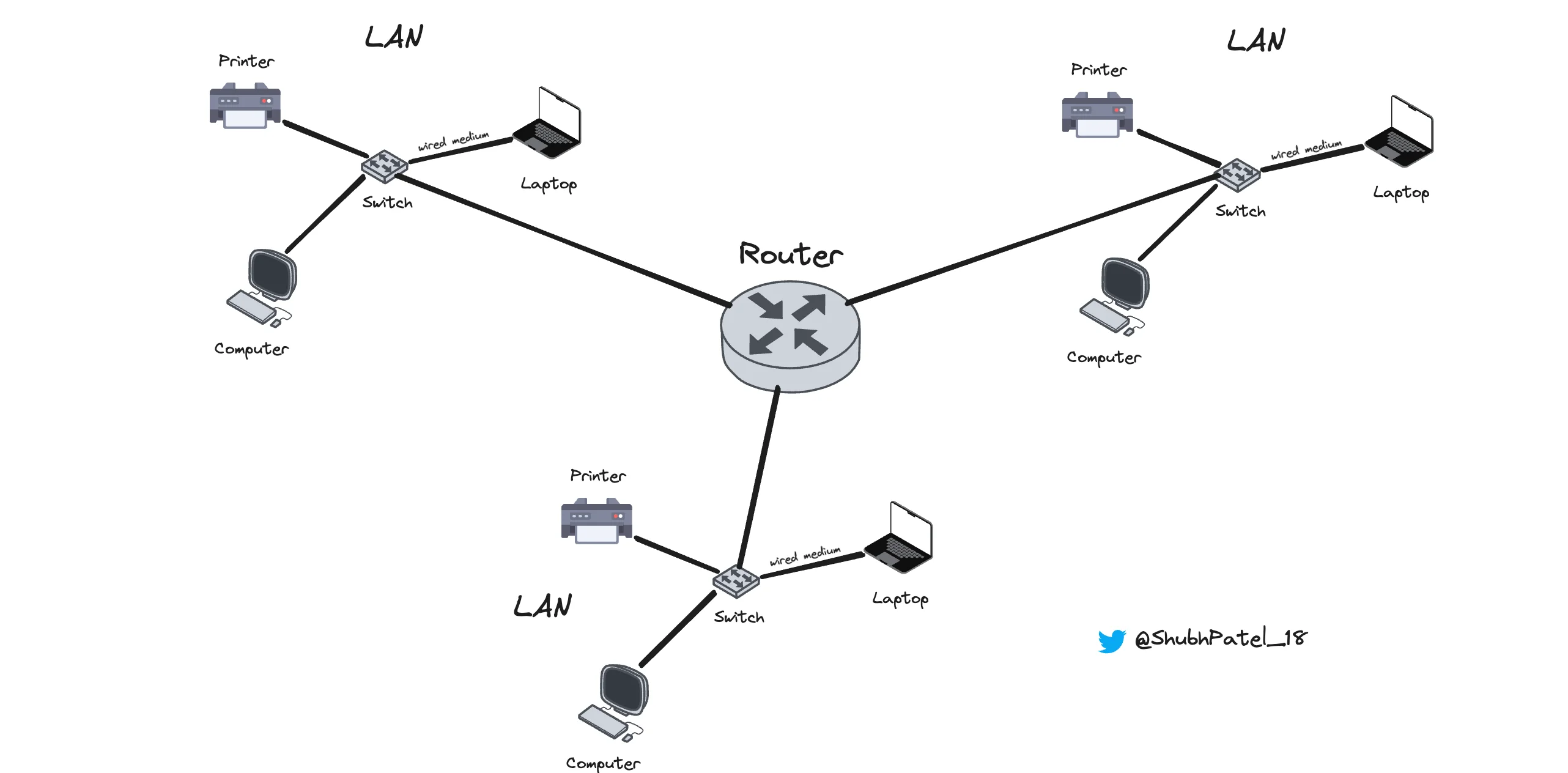
Routers are more advanced devices that connect multiple networks (such as LANs, MANs, and WANs). Routers operate at Layer 3 of the OSI model, allowing them to perform routing functions.
What is Routing?
Routing involves moving data across different networks. Here’s a simplified overview:
-
Network Connection: A router has multiple network interfaces, each connected to a different network. For instance, one could be connected to a LAN and another to the WAN (like the internet).
-
Routing Table: Routers maintain a routing table that helps determine the best path for data to travel across networks.
-
Packet Forwarding: When a data packet arrives at the router, it checks the packet's destination IP address and uses its routing table to decide the best path to forward the packet.
-
Network Address Translation (NAT): Routers often perform NAT, allowing multiple devices on a LAN to share a single public IP address. This function translates private IP addresses into a public IP address and vice versa, effectively managing IP address usage.
-
Firewall and Security: Many routers have built-in firewalls that control incoming and outgoing traffic, providing an extra layer of security by blocking unauthorized access.
Example of a Routing Table
| Network Destination | Subnet mask | Gateway | Flag | Outgoing Interface | Metric |
|---|---|---|---|---|---|
| 182.168.2.6 | 255.255.255.0 | 11.0.1.2 | U | eth02 | 1 |
-
Network Destination: This is the destination IP address or network. In this case,
182.168.2.6represents a specific network where the destination device is located. -
Subnet Mask: Defines the range of IP addresses within the network. A mask of
255.255.255.0indicates that the first three octets identify the network, and the last octet identifies the host. -
Gateway: The IP address of the next-hop router or gateway. Here,
11.0.1.2is the router that will take packets to the182.168.2.6network.
The key difference between a router and a gateway is that a router connects networks that follow the same protocol, whereas a gateway connects networks that follow different protocols.
-
Outgoing Interface: The network interface through which packets should be sent. In this example, it's
eth0, typically an Ethernet port. -
Metric: This value helps decide the best path when multiple routes to the same destination exist. Lower metrics are preferred.
-
Flag: Indicates the route status, such as
Ufor operational routes.